Settings
 Fast Delivery
 Payment Types


 Marketplace Product

Mfr Part # ST0012
HC-SR501 INFRARED SENSOR MODULE
SunFounder

License: None
Motion detection is a fundamental function in many embedded systems. An automatic light needs to know when someone enters a room, a security system needs to detect movement in a monitored area, and a smart-home controller may need to determine whether a space is occupied. A PIR (Passive Infrared) sensor provides a simple way to add this capability to an electronic design.
The HC-SR501 is a commonly used PIR motion sensor module that detects movement by sensing changes in infrared radiation. Unlike an active sensor, it does not transmit energy toward the target. Instead, it monitors the infrared radiation naturally emitted by objects in its field of view and produces a digital signal when it detects a change.
The module combines a pyroelectric sensing element, Fresnel lens, signal-processing circuitry, voltage regulation, and configurable timing and sensitivity controls. This makes it particularly useful for prototyping motion-detection circuits and experimenting with microcontroller-based designs.
This article explains the operating principle of the HC-SR501, its internal hardware, pinout, trigger modes, adjustment controls, specifications, and connection to an Arduino UNO.
A PIR sensor detects changes in infrared radiation emitted by objects in its surroundings. Every object above absolute zero emits infrared energy, and the human body continuously emits infrared radiation because of its body temperature.
The HC-SR501 does not actively transmit infrared energy. Instead, it monitors the infrared radiation arriving from its surroundings. When a warm object such as a person moves through the sensor's field of view, the amount and distribution of infrared radiation reaching the sensing element changes.
Two key components make this detection possible: the pyroelectric sensor and the Fresnel lens. The pyroelectric sensor responds to changes in infrared radiation, while the Fresnel lens focuses incoming infrared radiation onto the sensing element and provides a wider detection area.
This means the HC-SR501 is primarily a motion detector. It is not intended to measure the absolute temperature of an object.
The pyroelectric sensor is the sensing element responsible for detecting changes in infrared energy. It contains a pyroelectric material that produces an electrical charge when the infrared radiation reaching it changes.
The sensing element contains two infrared-sensitive sections. Their arrangement allows the sensor to reject changes that affect both sections equally while responding to differences between them.
When the environment is stationary, both sections receive approximately the same infrared radiation. Their outputs therefore tend to cancel, resulting in little or no differential signal.
When a person moves across the detection area, one section is affected before the other. This produces a positive differential change. As the person moves across the sensor and affects the second section, the differential signal changes in the opposite direction.
The electronics on the HC-SR501 process these changes and use them to determine whether motion has occurred.
This differential arrangement is particularly useful for motion detection because the sensor responds to changes in the infrared radiation pattern rather than simply responding to a constant background infrared level.
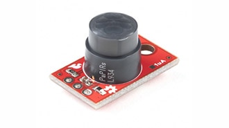
The white dome covering the HC-SR501 is a Fresnel lens. It consists of a series of concentric grooves that refract incoming infrared radiation and direct it toward the pyroelectric sensor.
The Fresnel lens allows the optical system to remain compact while providing a wide field of view. It also creates multiple detection zones across the sensor's coverage area.
As a warm object moves through these zones, the infrared radiation reaching the two sensing sections changes. This variation produces the differential signal required for motion detection.
The lens therefore has an important role in determining the sensor's detection area and how movement is presented to the pyroelectric sensing element.
The HC-SR501 has three primary pins: VCC, GND, and OUT.
The VCC pin provides power to the module. The module can be powered from approximately 4.5 V to 12 V, with 5 V being a common choice when interfacing it with an Arduino UNO.
The GND pin is connected to the system ground.
The OUT pin provides the motion-detection signal. When no motion is detected, the output remains LOW. When motion is detected, the output becomes HIGH, typically around 3.3 V.
The digital output makes it straightforward for a microcontroller to determine whether motion has been detected.
The HC-SR501 integrates several functional blocks around the pyroelectric sensing element. Understanding these components helps explain how the module converts a small infrared-induced signal into a usable digital output.
The BISS0001 is the signal-processing IC used on the HC-SR501.
The signal generated by the pyroelectric element requires amplification and processing before it can be used as a digital motion signal. The BISS0001 performs this signal processing and helps filter noise and interference.
The result is a conditioned output that can be provided through the module's OUT pin.
Because the signal conditioning is already handled by the module, the Arduino does not have to directly process the small raw signal generated by the pyroelectric element.
The HC-SR501 provides two additional positions on the back of the PCB marked RT and RL.
The RL position can be used to connect an LDR or photoresistor. This allows the sensor to be adapted for applications where ambient light conditions are important, such as systems intended to operate in dark environments.
The RT position can be used with a thermistor or temperature-sensitive resistor. This can provide additional adaptability in environments where temperature conditions may affect motion detection.
A protection diode is included on the module to help protect the circuit from reverse-voltage conditions.
This provides an additional level of protection during hardware prototyping and testing.
The module includes a 3.3 V voltage regulator for its internal circuitry. This allows the HC-SR501 to accept a higher external supply voltage while maintaining the appropriate internal operating voltage.
The presence of the regulator allows the module to be powered from the specified input range rather than requiring a separate regulated 3.3 V supply.
The module provides two trigger modes, selected using the onboard jumper: single trigger mode and multiple trigger mode.
The difference is primarily in how the output behaves when additional movement is detected while the output is already HIGH.
In single trigger mode, the OUT pin goes HIGH when motion is detected and remains HIGH for the selected delay period.
If another motion event occurs while the output is still HIGH, the sensor ignores that event. It can generate another HIGH pulse only after the existing output pulse has returned LOW.
This mode is useful when each motion event should produce an individual output pulse.
In multiple trigger mode, the sensor can respond to additional motion while the output is already HIGH.
When another motion event occurs during the active HIGH period, the output timing is reset or extended. This allows the output to remain HIGH when movement continues to be detected.
This mode is useful for applications such as automatic lighting, where continued movement should prevent the output from timing out prematurely.
One of the potentiometers on the HC-SR501 controls the sensitivity of the sensor.
The typical detection distance can be adjusted between approximately 3 m and 7 m. Rotating the potentiometer clockwise increases sensitivity, while rotating it counterclockwise decreases sensitivity.
The practical detection distance depends on the target, installation conditions, ambient temperature, sensor orientation, and movement direction. Therefore, sensitivity should be adjusted according to the requirements of the final application.
The second potentiometer controls the duration for which the OUT signal remains HIGH after motion is detected.
Turning the potentiometer clockwise increases the delay, while turning it counterclockwise decreases the delay.
This provides flexibility when integrating the module into different systems. A motion-controlled light, for example, may need a longer active period, while a microcontroller application may only need a short pulse to register a motion event.
A microcontroller is not required for every HC-SR501 application. Since the module performs its own signal processing and provides a digital output, the OUT signal can be used to control an external circuit through suitable interface circuitry.
For example, an LED can be connected to the output through a current-limiting resistor. When movement is detected, the OUT pin goes HIGH and the LED turns on.
This standalone configuration is also useful when evaluating the sensor during hardware development. The sensitivity, delay, and trigger settings can be adjusted and tested without writing firmware.
After power is applied, the module should be given some time to stabilize and adjust to the infrared conditions of the surrounding environment before its motion-detection behavior is evaluated.
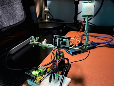
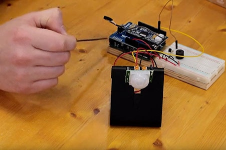
The HC-SR501 can be directly connected to an Arduino UNO because its OUT pin provides a digital signal.
The module is powered from the Arduino's 5 V and GND pins, and its OUT pin is connected to digital pin 2. The Arduino can then monitor this input to determine whether the sensor has detected motion.
A 16×2 LCD can be added to display the detection status. The LCD can be operated in 4-bit mode, which reduces the number of Arduino pins needed for communication.
The LCD RS pin is connected to Arduino pin 12, and the Enable pin is connected to pin 11. The LCD data pins D4, D5, D6, and D7 are connected to Arduino pins 6, 7, 8, and 9, respectively.
A 10 kΩ potentiometer is connected to the LCD VEE/Vo pin to adjust contrast. A 220 Ω resistor is used to limit the current through the LCD backlight.
The HC-SR501 can be used wherever a design needs a simple indication that movement has occurred within a particular area.
Common applications include automatic lighting, intrusion alarms, occupancy detection, smart-home automation, motion-triggered devices, and interactive electronic systems.
The module is particularly convenient for prototyping because the pyroelectric sensing element, signal-processing circuit, voltage regulator, and adjustment controls are already integrated.
For a production-oriented design, the same functional blocks can also be considered when developing a custom PCB. Instead of using the complete HC-SR501 module, a designer can integrate the required sensing and processing circuitry into a dedicated board according to the requirements of the application.
When integrating a PIR sensor into a hardware design, the physical placement of the sensor is just as important as the electrical interface. The Fresnel lens determines the optical field of view, while the sensitivity and delay controls determine how the module responds to movement.
The sensor should also be allowed to stabilize after power-up. Changes in the surrounding environment, temperature, and infrared background can affect the behavior of a PIR sensor, so testing should be performed under conditions similar to the final application.
For a simple Arduino prototype, the three-wire interface is sufficient. For a more integrated hardware design, however, the designer needs to consider the complete sensing chain, power supply, signal processing, output interface, and mechanical placement of the sensor.
The HC-SR501 is a practical PIR motion sensor module for detecting changes in infrared radiation. Its pyroelectric sensing element detects changes in infrared energy, while the Fresnel lens focuses the incoming radiation and provides a broad detection area.
The onboard BISS0001 controller processes the sensor signal and generates a digital output that can be read directly by an Arduino UNO. The module also provides adjustable sensitivity, adjustable output delay, and selectable single- and multiple-trigger modes.
With its simple VCC, GND, and OUT interface, the HC-SR501 is well suited to motion-detection prototypes and embedded electronics projects. Understanding how the sensing element, Fresnel lens, signal-processing IC, and configuration controls work together provides a useful foundation for integrating PIR-based motion detection into larger hardware systems.