Settings
 Fast Delivery
 Payment Types


 Marketplace Product
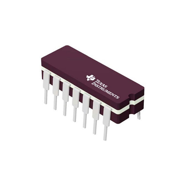
Mfr Part # NE556N
IC OSC TIMER DUAL 100KHZ 14-DIP
Texas Instruments

Breadboards LEDs / Discrete / Modules 555 Timer Wired
The goal of the project is to make an adjustable frequency circuit that could turn an LED on and off with a 555 timer so that it blinks at different rates. This post will cover the solderless breadboard prototype version. The end goal is to also make a printed circuit board through DKRed! I am waiting for my board to be fabricated at the moment, so that will come later. Here are the parameters I set for this project:
Here are three resources you should look at before reading the rest of the post:
The values work on paper with the calculations mentioned in the 555 datasheet, but they didn't quite match what happened on the physical prototype. Since Texas Instruments doesn't give guidance on selecting parts, I just thought that 50µF would be a good starting point. I kind of just ran through random values until all my resistances were positive using the equations in the datasheet. Here is the circuit diagram for my first prototype:

Keep in mind that the NE556N is a 14-pin dual timer; I only use half of it in my prototypes!
If you need general guidance for finding part numbers, you can refer to the values in the diagram or just aim for 1/4 to 1W resistors that are close enough to the values seen above. The closest potentiometer that I could find for R2 is 10k. For the prototype, it's fine to choose electrolytic capacitors. All you need is around 50µF rated for 5V or more (you can go quite a bit higher, and it still works). The 0.01µF capacitor can just be a simple through-hole ceramic capacitor rated for at least 5V. You can be off a little in the values because frequencies don't change that much for small changes. The reason I have a 110-ohm resistor after the potentiometer is to make a "floor" value. The potentiometer can reach zero or near-zero ohm values; this can be precarious for most circuits and can drive current way up! Yes, it will affect the upper value of R2, but again, frequency won't change that much.
I expected 60Hz, but noticed my light was flickering more than expected.
My light flickers slower than I expected. From experience, running an LED on AC voltage will still cause the light to flicker at 60Hz. This is barely visible to the naked eye. Here is a picture of the first breadboard prototype:

Clearly, the results are off. What is going on?
I wanted to measure the output from my timer using an oscilloscope. I have a 2190E from B&K Precision on my desk. Here are some screenshots of the data I imported into Excel using the CSV data:

Let's zoom in on one time period.

The datasheet for the 555 IC also includes formulas for T_High(time high) and T_Low(time low). The calculated time for TH should be around 0.402s. The calculated time for TL should be around 0.392s. My TH is pretty close, but my TL is a bit off. The effect is far more prominent at the "60Hz" end. My scope was only reading about 30Hz.


In this instance, TH is calculated to be around 0.0139s. TL is calculated to be around 0.0043 seconds. Again, my TH is close, but my TL is way off...there is about a 318% error!
Initially, I thought maybe my timer wasn’t functioning correctly. It turns out there is a lot more to selecting parts than I thought. I couldn’t figure out what was happening because my circuit was hooked up right, and I double-checked the calculations. This is the case where AI can be helpful in troubleshooting. It found an application note made by Philips called AN170. For context, if you aren’t sure what an application note is, engineers will often do a deep dive on a component and find design details that aren’t specified in datasheets. They will also reference outside sources to back up the claims they make. One particular note that is necessary can be found on page 6 under Selecting External Components:

In short, I was driving far too much current through the discharge NPN transistor Q14 on the internal design. As you reach the upper end of the current limits, you are driving up the Vce(sat) voltage; if you have a higher voltage drop, you will have more “resistance” added, which causes a timing error. Eventually, it actually could wear out the transistor too. Note that when I made my second prototype with the 5k minimum for Ra that I did not change the types of resistors and capacitors. The new resistor value does change the electrolytic down to 2.2uF.
Here is a new circuit diagram:

Instead of providing a picture of the new circuit on the breadboard, I challenge you to replace the values based on the original picture!
Here are the results for this new version on the O-scope:


The calculated TH should be around .317s, the observed is 0.34s. The new TL should be around 0.309s, the observed value is 0.320s. This is a lot more consistent. Again, it’s even more apparent at the higher frequency:


The frequency I read on my oscilloscope was about 59.5+ Hz. The calculated TH should be 0.0117s, the recorded value is 0.0112s. The calculated TL should be around 0.0041s, the recorded value is 0.004s. This is only 2% off! I think the results speak for themselves; the device is not faulty (my assumptions were).
a. They do give parameters to make sure you don’t burn the part out and often provide equations, but there was no guidance in selecting parts here.